


Hot Articles
-
How Are Hydraulic Presses Used to Make Ceramics?
Ceramics have many applications in our everyday lives – from housings and switches found in switching stations, to thermostats that regulate……
-
How to Make a Homemade Hydraulic Press
Hydraulic presses are highly effective tools capable of shaping metals and other materials with immense force, serving many industries as dependable……
-
Hydraulic Press Channel – How Much Does the Hydraulic Press You Tube Channel Make?
The Hydraulic Press Channel is a YouTube channel dedicated to crushing things with hydraulic presses. Founded by Finnish workshop owner Lauri Vuohen……
-
How to Make a Hydraulic Fruit Press
Hydraulic fruit presses provide a straightforward and cost-effective method of extracting juice from apples, pears, grapes, red currants or other fr……
-
How to Make a Small Hydraulic Press
Shopping can be challenging, particularly for something as complex and expensive as a hydraulic press. Such large purchases require much considera……
-
How to Make a Hydraulic Press For Forging
Hydraulic presses are essential tools for shaping and forming metal. Their force far surpasses that generated using mechanical hammer-and-anvil me……
-
How to Make Almond Oil With Hydraulic Press
Almond oil is an extremely versatile source of fats that can be used both for culinary and beauty uses, including hair and skin health benefits. Unr……
-
How Much Does a Hydraulic Press Cost?
Hydraulic presses are indispensable tools that play an essential part in shaping our world, with each press cycle. When purchasing or replacing an……
How to Make a Hydraulic Press Model
time:2023-12-02 views:(点击 1,282 次)
Hydraulic presses are unrivaled when it comes to crushing items, yet their costs may make commercial models prohibitively expensive.
By gathering up some scrap steel, and creating your own bolt together version, instead. Begin with the frame. Find an inexpensive source of "U" or "IL" channel and cut four side pieces to length.
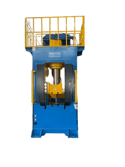
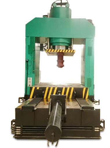
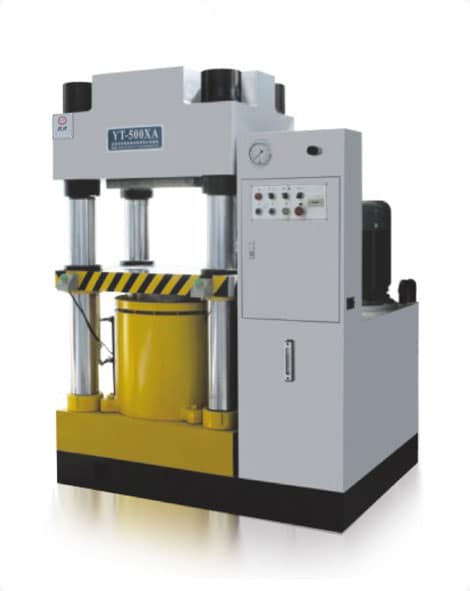
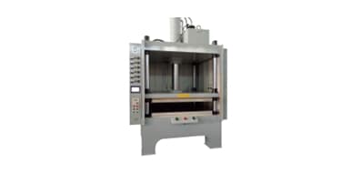
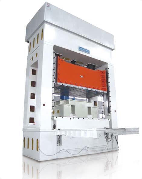
Frame
Hydraulic presses consist of strong steel structures that house their hydraulic ram. This component applies pressure on anvils and dies by way of hydraulic fluid flowing through cylinders; their number, diameter and design depend upon which model of press is being used; some even come equipped with larger ports for taking in hydraulic fluid while smaller ports allow it to exit through different ports for output.
A welded hydraulic press frame is an ideal choice for applications that demand high loads and force, such as metal-forming applications requiring complex shapes. Furthermore, it's essential to consider how often it will be operated per shift as this will help determine what type of hydraulic press will best meet these criteria.
Before beginning construction on your hydraulic press, it's essential that you determine its appropriate size and capacity for your application. To do this, ask yourself three questions: 1) What will be the size of the largest work piece? This will determine throat size (horizontal opening and daylight requirements); 2) What maximum tonnage requirement must be met to apply maximum pressure; and 3) When will the press need to operate quickly enough that manual or electric hydraulic presses may be best? Using electronic hydraulic presses reduce wear-and-tear costs on equipment as well as increase productivity while saving money over time compared with manual presses
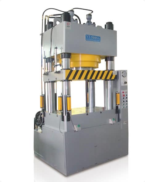
Cylinder
Hydraulic cylinders feature two ports that enable input and output of hydraulic fluid, making it an integral component of any hydraulic system. Components including its head, cap, cylinder barrel and piston rod must all be properly sized in order to facilitate laminar hydraulic fluid flow through its ports and prevent cavitation; additionally the material used must withstand pressure, temperature and environmental stress in which it will operate.
Establishing the appropriate cylinder size for an application can be challenging. Improperly sized cylinders may fail to lift loads or cause injury to equipment and people. Selecting the ideal cylinder can save both time and money as it eliminates wasted trips back to a shop for larger models.
Force produced by cylinders is calculated as the result of system pressure multiplied by piston internal surface area where this pressure acts. To accurately calculate this, one must know both piston diameter and stroke; additionally, one should understand how gravity effects on this piston can alter required cylinder sizes.
Your hydraulic press may utilize either one or two cylinders as its source of power. Paralleling them will increase force application; just be mindful of any differences in height or piston diameter between them.
Jack cylinders are standard-sized and mobile, making them easy to transport from job site to job site. Hand pumps may also be used with this equipment for lifting jobs requiring heavier lifting. Companies often rent them on an as-needed basis rather than keeping one permanently on site, making this cost effective option suitable for businesses that require frequent heavy lifting services.
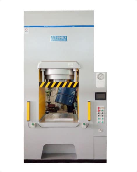
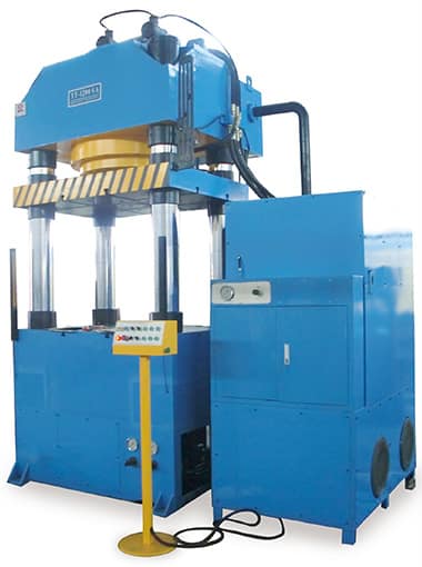
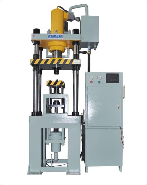
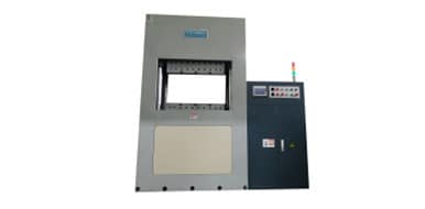
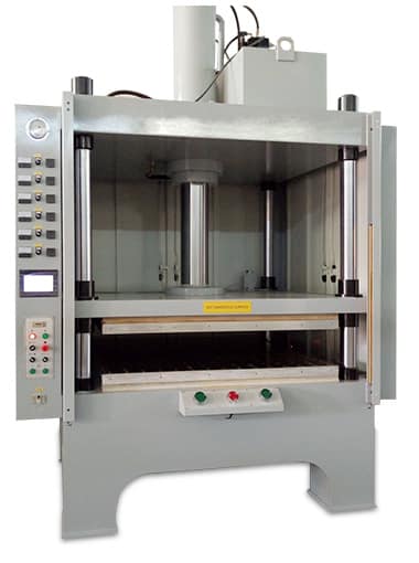
Platen
The platen of a hydraulic press is the surface against which its hydraulic ram presses; it may be made of steel, plastic, or another material and typically serves as a flat surface that facilitates printing or pressing materials such as paper and cardboard. Furthermore, some applications use platens as fingerprint image capture devices.
A typical hydraulic press machine consists of a frame which houses the hydraulic cylinder, along with a platen that applies immense pressure. Attachment options for the platen include bolting it on or welding it directly to the cylinder - although welding models tend to be more durable and difficult to create.
An industrial-sized hydraulic press can cost thousands of dollars; however, you can create your own smaller version for much less money and with greater ease. When constructing a hydraulic press it should be kept in mind that it will be heavy - therefore work gloves and protective helmet are highly recommended as part of the safety precautions to use this machine safely. Furthermore, ensure your bottle jack or hydraulic jack has been fully tested prior to using it!
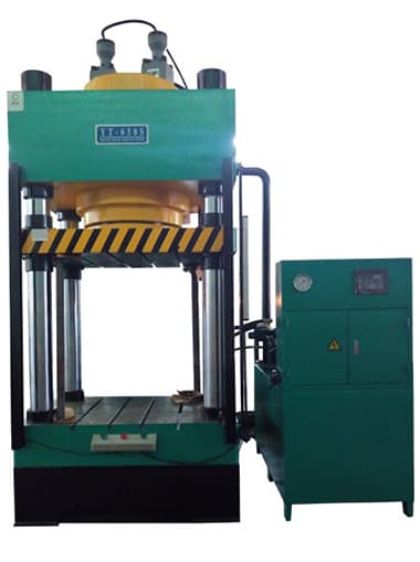
The moving platen 6 of this hydraulic press model is supported by two support rollers 13 mounted on machine bed 3 that rotatably support it lateral peripheral zone of moving platen 6. Drive unit 9 includes belt drive consisting of belt 9b that ties around rotatable pulleys 9a located concentric with spindle mechanisms 7. Both spindle nuts 8 and drive mechanism 7 operate in sync with each other for smooth functioning of moving platen 6.
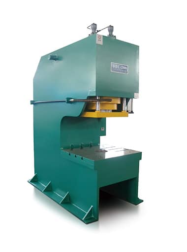
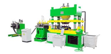
Hydraulic Pump
Hydraulic presses produce huge forces to perform tasks like crushing materials, clamping forces creation and other jobs requiring significant mechanical advantage. These forces are generated through pressurized hydraulic fluid flowing through its cylinder and pump and controlled by its control cylinder; powering these hydraulic systems may come from electricity, an electric motor or combustion engines.
Hydraulic piston pumps are the simplest form of hydraulic pumps, comprised of multiple pistons in a rotating cylinder block that rotates with its shaft. When activated by rotating shaft, these pistons move in and out of their respective chambers, drawing hydraulic oil from their supply ports into their outlet ports while forcing it out through an outlet port. They ride on an inclined plate called a "swash plate", which controls their stroke length to either increase or decrease volume within each cycle.
Piston pumps come in both fixed and variable displacement designs. Variable displacement models are often utilized in industrial settings like forklifts while fixed displacement pumps are used more commonly in construction equipment and heavy machinery like cranes and tractors. A hydraulic motor converts electrical energy to mechanical energy that drives piston pumps while an associated control valve provides system controls.
Hydraulics and pneumatics both function similarly, by transferring mechanical energy from mechanical sources into an oil or air medium and back out again as forceful force that completes tasks. A pump must create pressure for hydraulic systems to function, with specific types depending on which jobs the machine must complete; most commonly used pumps include vane, gear and piston pumps - to learn more about them all visit Lunchbox Sessions online hydraulics training resources.
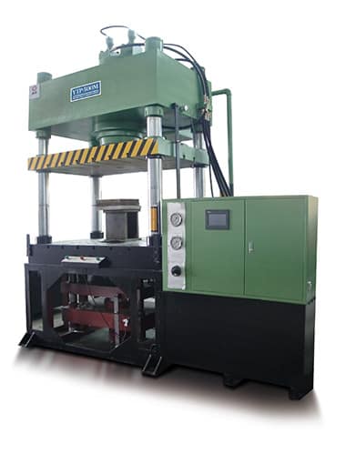
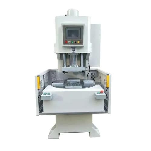
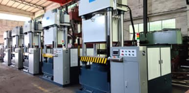
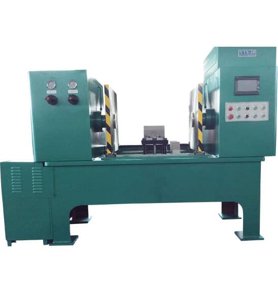
Motor
Hydraulic presses use fluid pressure to push a cylinder at a set force, and are commonly used for compressing, assembling, drawing, punching, trimming, stretching stamping or forming materials in various applications. They operate according to Pascal's principle which states that pressure exerted by an object remains constant regardless of where it lies; their operation requires both pump and motor for pressure generation which can reach up to 8,000 tons!
Hydraulic cylinders feature pistons made of metal that move vertically inside their cylindrical housings, filled with hydraulic oil to produce force when the piston is pushed upward. Furthermore, these systems include control systems which transform fluid power into mechanical energy to power its piston.
This system is powered by a motor that pumps hydraulic oil directly into a cylinder's cap and rod end ports, where pressurizing its cap end extends it and pressurizing its rod end retracts it. Pressurization at either end forces its extension or contraction; pressure generated from these mechanisms transfers to an even larger master cylinder to generate force that can press, bend and form materials.
Limit switches are used to adjust the height and thickness of material being compressed between platens, as well as maintaining an even gap between them. Furthermore, each machine features a manual control valve for regulating pressure applied to workpieces while its relief valve releases any excess pressure. Finally, its electrical box controls switches and joysticks using wiring or circuit connections; many different kinds of hydraulic press machines follow this same principle of operation - some pre-engineered for cost efficiency with heated platesns and automation equipment, others provide full automation control via switches and joysticks - each operating using similar principles but different mechanisms based on these principles based on these same principles; some even come pre-engineered for cost efficiency; others provide options like heated platesns or automation equipment as supplements to keep control.
Link to this article: https://www.ihydraulicpress.com/nsn/5640.html
Hot Articles
-
How Can Make a Small Hydraulic Hot Press?
Hydraulic presses offer powerful force that cannot be rivaled by other material shaping techniques. Hydraulic presses come in all shapes and sizes……
-
How to Make a Ring Using a Hydraulic Press
A hydraulic press uses Pascal’s law to generate massive forces. It consists of a strong metal frame into which is fitted a hydraulic cylinder;……
-
How to Make a Hydraulic Press at Home
Are You Needing an Hydraulic Press? However, these machines tend to be costly – fortunately you can make one yourself! Your introduction shoul……
-
How to Make a Hydraulic Forging Press
Hydraulic forging presses are indispensable tools for metalsmiths, serving to cut, bend, shape, and press metal into various forms. Furthermore, t……
-
How to Make a Hydraulic Press Brake
Press brakes are machines used for bending metal and other materials. They consist of a bed, a ram and dies to bend them according to their design; ……
-
How to Make a Hydraulic Apple Press
Hydraulic apple presses are an efficient way of turning ground apples into juice, and are easily assembled once you understand how they operate. L……
-
How to Make a Powerful Hydraulic Press
Hydraulic presses are powerful machines that use hydraulic fluid to transfer energy according to Pascal’s law, often for shaping metal, stam……
-
How to Make a Small Hydraulic Press
Hydraulic presses are heavy shop tools used for producing precision and symmetry in your workshop. They feature two cylinders, with different maxi……
Latest News
-
How to Make Hydraulic Press Brake
Press brakes are essential parts of any metal fabrication shop, yet many professionals and amateur fabricators struggle with understanding them. Pre……
-
How to Make a Hydraulic Press Machine
For heavy duty metalwork projects, hydraulic presses can provide invaluable assistance. These machines utilize hydraulic jacks to generate enormous ……
-
How to Make a Hydraulic Heat Press Machine
Hydraulic presses utilize Pascal’s law to multiply small forces applied over an area into greater ones. They’re highly versatile and use……
-
How to Make a Hydraulic Heat Press Machine
Hydraulic presses are unrivaled when it comes to creating complex shapes. Renowned for their versatile capabilities such as forging, stamping, cold ……
-
How to Make a Small Hydraulic Press
Hydraulic presses are heavy shop tools used for producing precision and symmetry in your workshop. They feature two cylinders, with different maxi……
-
How Much Does a 50000 Ton Hydraulic Press Cost?
Hydraulic presses are powerful machines capable of exerting large amounts of force onto objects. There are various kinds of hydraulic presses on t……
-

How to Make Your Own Hydraulic Brake Press
Hydraulic press brakes rely on a complex hydraulic system to achieve up and down movements of their ram during bending processes, by pumping oil th……
-
How Much Force Does a Hydraulic Press Exert?
Hydraulic presses play an integral part of many manufacturing processes. Utilizing Pascal’s Law, these powerful machines produce immense force……