


Hot Articles
-
How to Choose the Right Hydraulic Press for Your Needs
When looking for a press, whether it be one for your business or just personal use, it’s essential that you select one that meets your requi……
-
How to Find Hydraulic Press Repair Services
Hydraulic presses are essential machines that exert immense force on objects. They’re commonly employed in industries like blacksmithing and j……
-
How to Use a Disc Cutter on a Hydraulic Press
Disc cutters work beautifully when used with a hydraulic press, but setting them up can be challenging when using older sets from Contenti, Harbor F……
-
How to Maintain Hydraulic Press Components For Increased Efficiency
Hydraulic presses are employed in a variety of metal forming operations. These include compacting, assembly, punching, embossing and drawing. Hydrau……
-
How to Troubleshoot Hydraulic Press Issues
Hydraulic presses are a useful tool for deforming and milling materials. They’re often employed in the automotive industry to fabricate body ……
-
What Are the Hydraulic Press Automation System Repair Costs?
If you are in the market for retrofitting an existing hydraulic press or need to rebuild it, it is essential to understand what repair costs will be……
-
How to Find Hydraulic Press Automation System Repair Services
When your hydraulic press automation system isn’t performing as expected, it’s time to contact a repair company. There are some common……
-
Hydraulic Presses – What Are the Different Types of Hydraulic Presses?
Hydraulic presses are heavy-duty manual or semi-automatic machines used for various jobs. They feature an open frame, moving slabs, and exposed ge……
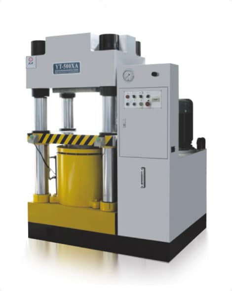
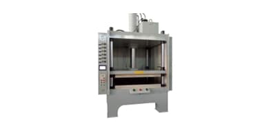
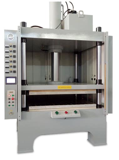
How to Integrate Hydraulic Press Automation Systems
time:2023-03-08 views:(点击 1,066 次)
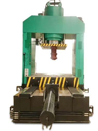
Hydraulic presses are widely employed in a range of industries. Automotive designers rely on them to fabricate parts for cars and trucks.
Controlling the force of a hydraulic press's ram is essential for automation. To accomplish this, store the accurate pressure and ram travel information in the controller's memory.
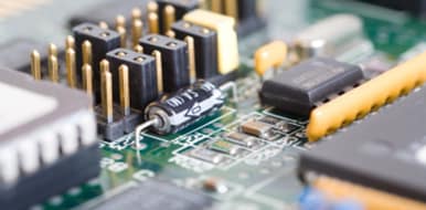
Inductive Sensors
Inductive sensors detect metal targets without physical contact by creating an electromagnetic field. This emitted magnetic alternating field interacts with the metal object, causing eddy currents to be generated. These extract energy from the sensor's LC oscillator, altering signal level within the detector and switching its output stage.
These sensors offer excellent performance under extreme temperatures, are resistant to the chemical corrosives used in food and beverage production, and are ECOLAB(r) certified. Constructed with one-piece stainless-steel (V4A/AISI 316L) housings and highly rated to IP68 and IP69K standards, these inductive sensors deliver ultimate accuracy and dependability at an economical price point - offering high-performance presence- and position sensing solutions at a great value.
KCC's automation system now prevents presses from progressing to tool change with incorrectly closed tools, reducing downtime and avoiding production faults that could damage either the tools or press itself. Furthermore, this PLC-based system automates direction reversal based on pressure measurements, guaranteeing parts are consistently pressed at an even depth and extending machine life.
PLC Controllers
A PLC (programmable logic controller) is an integrated computer capable of controlling various devices and components. Its input can include sensors that provide data about a process, while its output directs actuators such as electric motors or hydraulic cylinders.
A typical PLC has multiple input and output ports to communicate with various devices and components. Its internal memory stores programs and data that are programmed by the user.
For easier interaction between the operator and PLC, it can be equipped with a Human Machine Interface (HMI). This interactive panel displays visual representations of system health in real time.
Integrating a hydraulic press automation system requires using a PLC controller with an integrated HMI. This eliminates time-consuming and costly tasks such as PLC-Panel wiring and communication configuration.
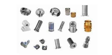
I/O Modules
I/O modules are used for connecting input and output signals to sensors or actuators. They come in various styles, offering features like isolation, termination and signal indication of the signal's status.
These I/O modules can be configured to accept discrete signals or analog data that changes over time, such as temperature, pressure or level. Some even offer burnout detection capabilities.
Leuze I/O masters support a range of protocols, such as PROFINET and Ethernet/IP. These enable process data, diagnostic information, and device details to be securely transmitted to higher systems or cloud applications. This system boosts machine adaptability and transparency while cutting maintenance/stocking costs by centrally commissioning sensors and actuators through web browsers.
Safety Circuits
There are various methods to protect an industrial hydraulic press operator or other plant personnel. Some are straightforward, like making sure they stay out of the way of moving machinery; however, other measures require design engineers to use more complex circuits and components.
One solution to this is using dual control circuits for cylinders. These allow for two-handed operation and are less taxing on operators than single controls.
These circuits often include a lock valve that prevents the cylinder from drifting or sagging, even when only one of the valves is shifted.
Another approach is to incorporate monitored safety valves into both the upstream and downstream process. The monitored valve is retrofitted into the system between the pump supply point and downstream process.
De-energising the valve isolates it from the pump and any residual energy in the downstream process is taken out. This information is then sent to your PLC via M12 connection.
Link to this article: https://www.ihydraulicpress.com/ht/1319.html
Hot Articles
-
How to Increase Hydraulic Press Automation System Productivity
When designing a custom hydraulic press for your application, it is essential that it be tailored to meet the particular demands of your operation……
-
The Hydraulic Press Tooling Repair Process
Hydraulic presses are versatile tools used for metal shaping and deforming. Because they generate full pressure throughout their stroke, they’……
-
Types of Hydraulic Press Tooling
Hydraulic presses are industrial machines used for fabricating metal parts. They’re also employed in welding, compacting food items, making in……
-
How to Manufacture Hydraulic Press Tooling
No matter if you’re in the aerospace parts, appliance components or food and beverage cans industry, hydraulic press tooling plays a pivotal……
-
Hydraulic Press Tooling Repair Services
Hydraulic presses are a staple of industrial equipment for many companies. But these powerful machines need regular repair and upkeep in order to re……
-
Advantages of Hydraulic Press Automation Systems
Are you searching for ways to increase production speeds, cut maintenance expenses or enhance machine efficiency? Hydraulic press automation systems……
-
Safety Procedures for Hydraulic Press Repair
Hydraulic presses are widely used in industrial settings, from cutting sheet metal to making powders and tablets. But like any machine, they can e……
-
How to Design Hydraulic Press Tooling
Hydraulic presses are indispensable in many industrial processes, from part production to compacting and crushing materials. Their speedy capabili……
Latest News
-
What Is a Small Hydraulic Press?
A small hydraulic press is an efficient tool that uses pressure to compact powdered materials. It has many uses, such as scrap baling and ceramics m……
-
How to Integrate Hydraulic Press Automation Systems Into Assembly Systems
As presses become more deeply embedded into larger assembly systems, it is becoming increasingly essential to collaborate with an automation speci……
-
The Benefits of Hydraulic Press Tooling
Hydraulic presses are an ideal choice for metalworking companies looking to maximize productivity and efficiency. Compared to mechanical presses, ……
-
Hydraulic Press Tooling Advantages
Hydraulic press tooling offers numerous advantages, such as safety, longer tool life, ease of adjustment and lower tool costs. Hydraulic presses are……
-
Industrial Hydraulic Press
Hydraulic presses are essential mechanical devices in many industries for fabricating, shaping or compressing materials. They use synthetic, water……
-
What Are the Parts of a Hydraulic Press?
Hydraulic presses are an indispensable industrial tool that can be employed in numerous industries. Automotive designers particularly benefit from……
-
Benefits of Hydraulic Press Repair Services
Hydraulic presses are a versatile piece of equipment used in many fields. They’re especially beneficial to industries such as agriculture, man……
-
Hydraulic Press Safety Procedures
Hydraulic presses are essential machinery in many industries. Unfortunately, their numerous uses and benefits come at the cost of serious safety ris……