How to Make an Electric Hydraulic Press
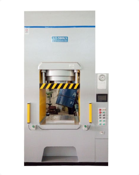
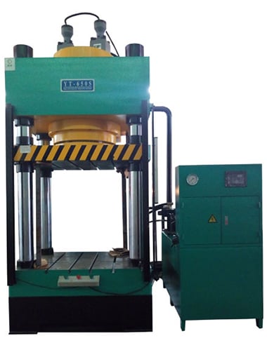
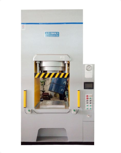
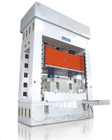
time:2023-07-28 views:(点击 683 次)Hydraulic presses are useful metal-forming machines used in factories for fabrication, assembly and maintenance purposes. They use a pump to generate pressure that pushes against material with set force against an extended hydraulic steel cylinder to form it into shape.
Pumps may be electric, pneumatic or hand operated depending on the press type. No matter their power source, all pumps transform mechanical energy into fluid pressure energy.
1. Hydraulic Cylinder
Hydraulic presses play an integral part in manufacturing and production processes. From shaping machine parts to straightening long shafts and compressing powdered materials, hydraulic presses play an integral part of many operations.
Hydraulic presses work by employing a cylinder and piston, together with incompressible fluid pressure, to generate mechanical force through mechanical action. A hydraulic system allows force generation in both directions with less force required than when manually pressing. This provides greater precision and efficiency when operating such presses.
Hydraulic cylinders come in various forms - vertical, horizontal and rotary. Each uses different pipework, valves and logic arrangements to generate motion and force for specific applications.
When switching from hydraulic cylinders to electromechanical actuators, it is crucial that you understand how to calculate the necessary force so the replacement actuator fits perfectly for your application. Any errors can lead to an oversized actuator which increases costs and challenges ROI. To calculate this force accurately, pressure measurements at both blind-ends of a hydraulic cylinder must be recorded, and subtracted from rod-end pressure using Force = Area x Pressure formula as follows.
Calculating the force of a hydraulic cylinder can be done many different ways, each method having its own set of advantages and disadvantages. One common miscalculation when transitioning from hydraulic to motor actuator use involves using system pressure as the basis of force calculation; this may result in oversizing electric actuators with higher initial costs and difficult return on investments (ROIs).
To calculate force requirements accurately, it is advisable to utilize a pressure gauge near the ports of the hydraulic cylinder and measure its differential pressure output between its ends. With this information and the formula in hand, one can accurately size their hydraulic piston while selecting an electromechanical actuator suited for their system - not only resulting in accurate force measurements but also reduced friction and wasted energy within their system.
2. Pressing Plates
Hydraulic presses are widely utilized across industries for fabrication, assembly and maintenance tasks. Utilizing hydraulic fluid, they use forceful pushes against materials using steel cylinders at an adjustable pressure setting - many supporting up to 12,000lbs! There are various sizes and types of presses depending on their intended applications - each offering different sizes of benefits depending on specific circumstances and applications.
Pressing plates are machine parts used to apply pressure to material being pressed. Each pressing plate features its own collar connected to a hydraulic cylinder; this allows pressure applied by the ram to be managed and adjusted via these collars. In order for proper pressing to occur, each collar should be properly aligned and secured so as to press properly against each other while also fitting comfortably against whatever workpiece will be placed between them.
Pascal's principle outlines that when one piston is pushed, it creates a change in pressure throughout a restricted fluid area around that piston, creating an oscillatory motion in that fluid area and thus producing pressure change throughout its entirety. Hydraulic presses use this force to shape materials such as powdered metal into desired sizes and designs.
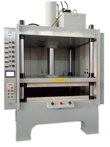
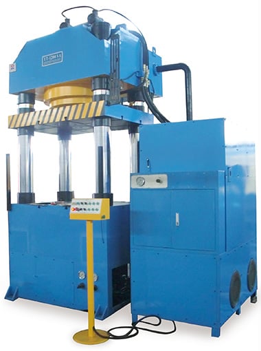
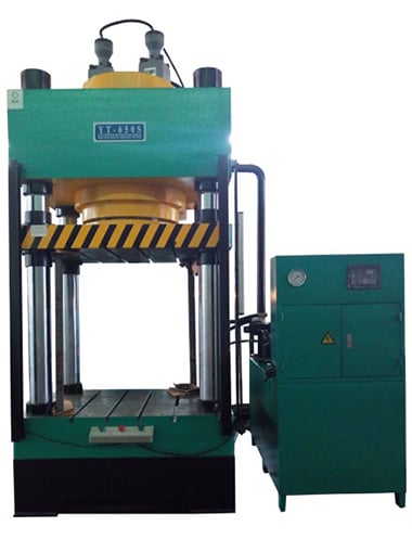
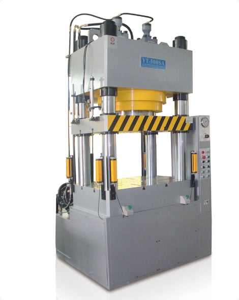
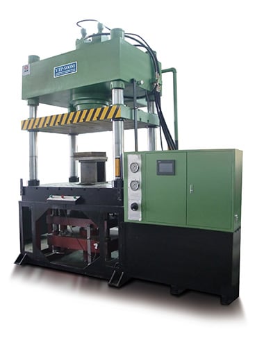
As one of the most versatile forms of hydraulic presses available today, two or four column models are particularly prevalent in manufacturing plants and other industrial settings due to their versatility and ability to accurately shape materials. These presses can handle material sizes ranging from simple automotive parts and designs all the way through electrical components and firearms - making them indispensable tools.
Hydraulic presses can be extremely cumbersome machines, making moving and positioning them difficult in certain settings. But you may be able to reduce their weight through design modifications that make alterations in design or material choices; such changes could have an incredible positive impact on a company's bottom line while helping it meet environmental regulations.
When operating a hydraulic press, it's critical to adhere to all manufacturer-provided instructions and safety regulations in order to avoid accidents and damages to equipment. Furthermore, prior to turning on the machine it's imperative that all wires and valves are correctly attached so as to prevent excess pressure being applied to workpieces as well as malfunction of device or injury of operator.
3. Power Source
Hydraulic presses use pressurized liquid as power, with this fluid exerting force onto a piston to compress materials together. A hydraulic press is designed so the user can adjust this force by increasing or decreasing pressure - this fluid can then be used to form and shape metal, plastics, and other materials into various forms and shapes. However, while hydraulic presses may produce tremendous force output, they should still be treated as dangerous machines which require proper training prior to using one.
Energy usage by hydraulic machines is an indicator of their power efficiency; however, due to their complex systems it can be challenging to ascertain the precise electric energy consumption of a hydraulic press. Therefore, this study seeks to investigate traditional hydraulic presses by analyzing active electricity consumption of their motor pumps using data acquisition cards and power meters which measure voltage and current instantly; results demonstrate that proposed hydraulic press consumes less energy.
Hydraulic systems consist of various functional systems, including the hydraulic forming and cooling systems. As a result, energy efficiency of hydraulic presses is often poor due to demand power exceeding installed power in most cases. To address this problem, researchers have designed an energy-saving system combining prefill and buffer systems, tested on a 13 MN forging hydraulic press, which has demonstrated its energy-saving potential.
Experiments demonstrate that the proposed system can save significant energy by combining the prefill system and buffer system into one cohesive package. Energy savings result from reduced strain on main working cylinders as well as reductions in overflow losses during PM stage and throttling losses during unloading stage due to use of buffer system.
4. Limit Switch
Electric hydraulic presses offer all the force of traditional mechanical presses while being much cheaper, as well as being oil and gas free and with shorter stroke requirements than their counterparts. Used to crush rocks, bottles and jars - an electric hydraulic press can make an excellent home handyman project or hobby project in just an hour or two with great results - just remember to wear safety goggles while crushing things so it doesn't shatter!
An electric hydraulic press differs significantly from its mechanical counterpart in that its power source is supplied by an electrical motor that drives series of hydraulic valves instead of using cams and crankshafts for controlling movement of ram and piston, which means it can achieve more cycles per minute than its mechanical counterpart.
Hydraulic circuits can operate more quickly due to having fewer "valve shifts", allowing the ram to travel down and back up with equal amounts of time, thus shortening overall cycle times.
As soon as the ram reaches its pre-set up position, a limit switch closes, activating control relays UPLSCR and DNLSCR to switch solenoids to their up positions and move upwards (Ill. 7). When reaching its lower limit limit switch DNLS closes and activating control relays DNLSCR and CR2 simultaneously; changing down solenoids back to their up positions as it moves downwards.
This system is intended to avoid any shock when the ram breaks through workpiece during breakthrough cycle. A tripping mechanism has been installed into its circuit that senses when male dies are approximately three-quarters through blank and activates an automatic switch for pressure release from cylinder head diverting it back to tank and thus lowering work pressure, so breakthrough occurs without substantial impacts or shocks. Furthermore, at this point ram down-limit switch will also trigger so as to relieve excess working pressure before returning back and prevent overpressure in cylinder head before returning ram return preventing overpressure in cylinder head.
Link to this article: https://www.ihydraulicpress.com/nsn/4039.html
Hot Articles
-
How to Make a Hydraulic Press
Hydraulic presses utilize hydraulic cylinders to produce compressive forces based on Pascal’s law using incompressible fluid, usually hydrauli……
-
How Can Make a Small Hydraulic Hot Press?
Hydraulic presses can be indispensable tools in garages. Used to repair bearings and silent blocks, as well as produce fuel briquettes, they have ……
-
How to Make a Hydraulic Press
Hydraulic presses are metal-forming machines that utilize hydraulic equivalents of levers to generate immense force, with the ability to apply and c……
-
How to Make a Hydraulic Press With Cardboard
Hydraulic presses are machines used to compress solid materials. They are especially helpful for recycling cardboard. An affordable DIY hydraulic ……
-
How to Make a Small Hydraulic Press
Shopping can be challenging, particularly for something as complex and expensive as a hydraulic press. Such large purchases require much considera……
-
Calculating How Much Force in Hydraulic Press
Hydraulic presses are powerful machines used across industries for everything from creating metal car parts to crushing waste and trash, creating ……
-
Who Makes Black Widow Hydraulic Press?
Hydraulic presses can be an invaluable asset when it comes to metalwork projects. From bending and straightening metal, loosening parts that have ……
-
How Much Is Hydraulic Press?
Hydraulic presses are ideal machines for stamping metal and molding rubber, offering precision shaping of various materials at an economical cost. W……
Latest News
-
How to Make a Hydraulic Heat Press Machine
The hydraulic press is a versatile machine used to accomplish various tasks. Common uses for it include forging, stamping, cold extrusion, bending, ……
-
How Much Does the Hydraulic Press YouTube Channel Make?
The Hydraulic Press Channel has amassed an enormous following on YouTube by using hydraulic presses to crush various objects, created in October 2……
-
How to Make Home Hydraulic Press
Hydraulic presses are multipurpose tools, capable of stamping, piercing, flattening and forging materials as well as crushing and folding them. Hy……
-
How to Make a Hydraulic Press Machine
A hydraulic press employs Pascal’s principle to generate tremendous force. The machine features two cylinders; the smaller one contains the ……
-
Does Hydraulic Press Make Things Heat Up?
Hydraulic presses have applications in numerous sectors, from fruit juice production to vehicle repair shops. Hydraulic presses can help squeeze eve……
-
How to Make Small Hydraulic Press at Home
Every garage master knows that having access to a press can be invaluable when repairing bearings, silent blocks or simply packing more compactly. W……
-
How to Make a Hydraulic Press at Home
Hydraulic presses can be used for various metal shaping and deforming operations, providing immense force application while offering both customiz……
-
How to Make Hydraulic Press Pocket Super-Viral Videos
Hydraulic Press Pocket will keep you entertained with its stunningly realistic collision simulation, where Finnish workshop owner Vuohensilta uses……
